sys-ok Fans Club
Sobat Mau Jago Soal Hardware?? Klik Di Sini!!


Tampilkan postingan dengan label LPT. Tampilkan semua postingan

Senin, 18 Februari 2013

Accessing PC Parallel Port (LPT Port) With Borland Delphi 7.0 Using Small Port Component


Posted by To Share Wednesday, 24 August 2011 0 comments
Adsense Content. recommended 336 X 300
This article will lead you how to make a program to access input output data in parallel port, simple example, this program is used to turn on and turn of LED which is set in Parallel Port, Data Register in computer (Pin D2 until pin D9) in Parallel Port/ LPT.
The steps are as follows:
Enter the following component in Form 1:

No Component Property Value
1 Shape1 Name ShpLED1
Shape stCircle
Height 41
Width 41
Brush Color clWhite
Brush Style bsSolid
2 Shape2 Name ShpLED2
Shape stCircle
Height 41
Width 41
Brush Color clWhite
Brush Style bsSolid
3 Shape3 Name ShpLED3
Shape stCircle
Height 41
Width 41
Brush Color clWhite
Brush Style bsSolid
4 Shape4 Name ShpLED4
Shape stCircle
Height 41
Width 41
Brush Color clWhite
Brush Style bsSolid
5 Shape5 Name ShpLED5
Shape stCircle
Height 41
Width 41
Brush Color clWhite
Brush Style bsSolid
6 Shape6 Name ShpLED6
Shape stCircle
Height 41
Width 41
Brush Color clWhite
Brush Style bsSolid
7 Shape7 Name ShpLED7
Shape stCircle
Height 41
Width 41
Brush Color clWhite
Brush Style bsSolid
8 Shape8 Name ShpLED8
Shape stCircle
Height 41
Width 41
Brush Color clWhite
Brush Style bsSolid
9 EditText1 Name EdLED1
Text -
10 EditText2 Name EdLED2
Text -
11 EditText3 Name EdLED3
Text -
12 EditText4 Name EdLED4
Text -
13 EditText5 Name EdLED5
Text -
14 EditText6 Name EdLED6
Text -
15 EditText7 Name EdLED7
Text -
16 EditText8 Name EdLED8
Text -
17 Button1 Name BtnNyalaLED1
Caption NyalakanLED1
18 Button2 Name BtnNyalaLED2
Caption NyalakanLED2
19 Button3 Name BtnNyalaLED3
Caption NyalakanLED3
20 Button4 Name BtnNyalaLED4
Caption NyalakanLED4
21 Button5 Name BtnNyalaLED5
Caption NyalakanLED5
22 Button6 Name BtnNyalaLED6
Caption NyalakanLED6
23 Button7 Name BtnNyalaLED7
Caption NyalakanLED7
24 Button8 Name BtnNyalaLED8
Caption NyalakanLED8
25 Button9 Name BtnMatiLED1
Caption MatikanLED1
26 Button10 Name BtnMatiLED2
Caption MatikanLED2
27 Button11 Name BtnMatiLED3
Caption MatikanLED3
28 Button12 Name BtnMatiLED4
Caption MatikanLED4
29 Button13 Name BtnMatiLED5
Caption MatikanLED5
30 Button14 Name BtnMatiLED6
Caption MatikanLED6
31 Button15 Name BtnMatiLED7
Caption MatikanLED7
32 Button16 Name BtnMatiLED8
Caption MatikanLED8
33 Button17 Name BtnOpenPort
Caption Open Port
34 Button18 Name BtnClosePort
Caption CloseProgram
35 SmallPort1 Name SmPort1


In the monitor will appear image like the following;  
 
Picture1. Accessing PC Parallel Port (LPT Port) With Borland Delphi 7.0 Using Small Port Component : Visualization of the Program which will be made.
Before making listing program (source code) first we decide 2 variables which will be used; those are “data” and “NewData” which mean:
NO. NAMA KOMPONEN SOURCE CODE
1 BtnMatiLED1 data := SmPort1.ReadByte($378);
baru := data AND 254;
SmPort1.WriteByte($378,baru);
ShpLED1.Brush.Color := clBlack;
EdLED1.Text:='OFF';
2 BtnMatiLED2 data := SmPort1.ReadByte($378);
baru := data AND 253;
SmPort1.WriteByte($378,baru);
ShpLED2.Brush.Color := clBlack;
EdLED2.Text:='OFF';
3 BtnMatiLED3 data := SmPort1.ReadByte($378);
baru := data AND 251;
smport1.WriteByte($378,baru);
ShpLED3.Brush.Color := clBlack;
EdLED3.Text:='OFF';
4 BtnMatiLED4 data := SmPort1.ReadByte($378);
baru := data AND 247 ;
SmPort1.WriteByte($378,baru);
ShpLED4.Brush.Color := clBlack;
EdLED4.Text:='OFF';
5 BtnMatiLED5 data := SmPort1.ReadByte($378);
baru := data AND 239;
SmPort1.WriteByte($378,baru);
ShpLED5.Brush.Color := clBlack;
EdLED5.Text:='OFF';
6 BtnMatiLED6 data := SmPort1.ReadByte($378);
baru := data AND 223 ;
SmPort1.WriteByte($378,baru);
ShpLED6.Brush.Color := clBlack;
EdLED6.Text:='OFF';
7 BtnMatiLED7 data := SmPort1.ReadByte($378);
baru := data AND 191;
SmPort1.WriteByte($378,baru);
ShpLED7.Brush.Color := clBlack;
EdLED7.Text:='OFF';
8 BtnMatiLED8 data :=SmPort1.ReadByte($378);
baru := data AND 127;
SmPort1.WriteByte($378,baru);
ShpLED8.Brush.Color := clBlack;
EdLED8.Text:='OFF';
9 BtnNyalaLED1 data := SmPort1.ReadByte($378);
baru := data or 1;
SmPort1.WriteByte($378,baru);
ShpLED1.Brush.Color := clRED;
edLED1.Text:='ON';
10 BtnNyalaLED2 data := SmPort1.ReadByte($378);
baru := data or 2;
SmPort1.WriteByte($378,baru);
ShpLED2.Brush.Color := clRED;
edLED2.Text:='ON';
11 BtnNyalaLED3 data := SmPort1.ReadByte($378);
baru := data or 4;
SmPort1.WriteByte($378,baru);
ShpLED3.Brush.Color := clRED;
edLED3.Text:='ON';
12 BtnNyalaLED4 data := SmPort1.ReadByte($378);
baru := data or 8;
SmPort1.WriteByte($378,baru);
ShpLED4.Brush.Color := clRED;
edLED4.Text:='ON';
13 BtnNyalaLED5 data := SmPort1.ReadByte($378);
baru := data or 16;
SmPort1.WriteByte($378,baru);
ShpLED5.Brush.Color := clRED;
edLED5.Text:='ON'
14 BtnNyalaLED6 data := SmPort1.ReadByte($378);
baru := data or 32;
SmPort1.WriteByte($378,baru);
ShpLED6.Brush.Color := clRED;
edLED6.Text:='ON';
15 BtnNyalaLED7 data := SmPort1.ReadByte($378);
baru := data or 64;
SmPort1.WriteByte($378,baru);
ShpLED7.Brush.Color := clRED;
edLED7.Text:='ON';
16 BtnNyalaLED8 data := SmPort1.ReadByte($378);
baru := data or 128;
SmPort1.WriteByte($378,baru);
ShpLED8.Brush.Color := clRED;
edLED8.Text:='ON';
17 BtnOpenPort SmPort1.Opened:=true;
18 BtnCloseProgram Close;
            “Data” is value that will be read from parallel port in the form of 8 bit data (1 byte)
“New data” is value that will be written to the parallel port after conducted
“Modification” with logical “and” or “or” to conduct bit setting or bit clearing data which is written in the form of 8 bit data (1 byte)
Variable writing decision is conducted under the writing:
var
Form 1:Tform1;
The result is as follows: 
Picture 2. Accessing PC Parallel Port (LPT Port) With Borland Delphi 7.0 Using Small Port Component : variable declaration
The next step is how to make source code program comprehensively so that the program can be used:
Type source code below, appropriate with each component which mean:


result of program execution is like this:  
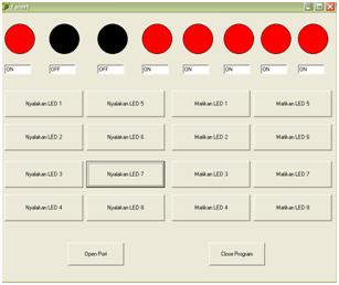

Picture 3. Accessing PC Parallel Port (LPT Port) With Borland Delphi 7.0 Using Small Port Component : The Result of Program Execution.

 I hope this writing can give benefit to the visitors, readers, developer and me. Thanks for visiting and availability for sharing this article by pressing Share To Facebook, Twitter button or just press like button.
Read More >>

Read more ...

Senin, 11 Februari 2013

Delphi dan Sistem Embedding – Port Serial RS-232


OK sekarang kita akan membuat contoh sederhana interfacing PC dengan mikrokontroler lewat port serial.
Di contoh ini, mikrokontroler digunakan untuk mengendalikan 4 LED dan membaca 4 saklar. Tugas komputer adalah mengendalikan ke-8 LED tersebut dan membaca posisi saklar.
Program Mikrokontroler
Mikrokontroler menggunakan sebuah AT89S52 dan menggunakan bahasa assembler. Berikut skematiknya.
Skematik ini tidak menampilkan rangkaian RS-232, hanya langsung menggunakan symbol COMPIM. Untuk rangkaian RS-232 converter bisa diliat di sini.
AT89S52 bekerja pada frekuensi 11.0592 MHz dan baud rate pada 9600 bps. Tugas utama mikro adalah selalu mengecek data dari port serial, sub-rutinCommand_Receive dan memproses perintah yang diterima, sub-rutinCommand_Process. Perintah menggunakan 1 karakter ASCII, ‘A’ – ‘G’.
Berikut adalah daftar perintah dari PC:
  • ‘A’: toggle LED yang terhubung ke P2.0
  • ‘B’: toggle LED yang terhubung ke P2.1
  • ‘C’: toggle LED yang terhubung ke P2.2
  • ‘D’: toggle LED yang terhubung ke P2.3
  • ‘E’: semua LED ON
  • ‘F’: semua LED OFF
  • ‘G’: membaca posisi saklar, jika saklar ON semua mikro akan mengirim ’00′ dan jika OFF semua mikro akan mengirim ’0F’.
Program mikro bisa di download di sini.
Pada dasarnya, mikro memfungsikan port serial pada mode 1 dengan baud rate 9600 bps. Pada saat dimulai program langsung menyalakan semua LED. Dan mikrokontroler sebagian besar menghabiskan waktunya untuk membaca command dari port serial.
Program Komputer
Tampilan program komputer bisa dilihat di bawah ini dan source codenya bisa di download di sini.
Bagian utama dari program Delphi adalah:
Prosedure EnumComport
Prosedure ini adalah prosedure untuk membaca registry untuk mengetahui COM apa saja yang terinstal di komputer. Berikut cuplikan kodenya:
procedure TForm5.EnumComPorts(Ports: TStrings);
var
KeyHandle: HKEY;
ErrCode, Index: Integer;
ValueName, Data: string;
ValueLen, DataLen, ValueType: DWORD;
TmpPorts: TStringList;
begin
ErrCode := RegOpenKeyEx(
HKEY_LOCAL_MACHINE,
‘HARDWARE\DEVICEMAP\SERIALCOMM’,
0,
KEY_READ,
KeyHandle);
if ErrCode <> ERROR_SUCCESS then
begin
//raise EComPortExt.Create(‘EnumComPorts’,CError_RegError, ErrCode);
MessageBox(Handle,’Registry Error’,pchar(Application.Title),MB_OK or MB_ICONERROR);
exit;
end;
TmpPorts := TStringList.Create;
try
Index := 0;
repeat
ValueLen := 256;
DataLen := 256;
SetLength(ValueName, ValueLen);
SetLength(Data, DataLen);
ErrCode := RegEnumValue(
KeyHandle,
Index,
PChar(ValueName),
{$IFDEF DELPHI_4_OR_HIGHER}
Cardinal(ValueLen),
{$ELSE}
ValueLen,
{$ENDIF}
nil,
@ValueType,
PByte(PChar(Data)),
@DataLen);
if ErrCode = ERROR_SUCCESS then
begin
SetLength(Data, DataLen);
TmpPorts.Add(Data);
Inc(Index);
end
else
if ErrCode <> ERROR_NO_MORE_ITEMS then
MessageBox(Handle,’Registry error’,pchar(Application.Title),MB_OK or MB_ICONERROR);
until (ErrCode <> ERROR_SUCCESS) ;
TmpPorts.Sort;
Ports.Assign(TmpPorts);
finally
RegCloseKey(KeyHandle);
TmpPorts.Free;
end;
end;
prosedur ini digunakan di event Combobox1 onDropdown:
procedure TForm5.ComboBox1DropDown(Sender: TObject);
begin
EnumComPorts(ComboBox1.Items);
end;
Pada saat ComboBox1 mengalami even Ondropdown, maka akan ditambahkan item2 baru berupa nama com yang terinstal di PC.
Prosedur Buka COM
ApdComport dibuka oleh button1, button dengan caption “Open”. Berikut cuplikan programnya:
procedure TForm5.Button1Click(Sender: TObject);
var
ComNo:integer;
S:string;
begin
if ComboBox1.ItemIndex=-1  then
begin
MessageBox(Handle,’Please select a COM’,pchar(Application.Title),
MB_OK or MB_ICONERROR);
ComboBox1.SetFocus;
exit;
end;
S:=Copy(ComboBox1.Text,4,Length(ComboBox1.Text)-3);
ComNo:=StrToInt(s);
try
ApdComPort1.ComNumber:=ComNo;
ApdComPort1.Open:=true;
Except
Port_State:=false;
end;
end;
Pertama program mengecek apakah COM sudah dipilih dengan membaca ComboBox1.Itemindex, jika bernilai -1, berarti belum ada com yang dipilih. Program akan menampilkan pesan error. Jika sudah ada com yang terpilih, program akan mengambil nomor comnya, dengan membuang string “COM”.
Lalu apdComport coba dibuka dengan membuat property open menjadi true. Jika gagal, misal karena com yang bersangkutan telah dipakai oleh aplikasi lain, maka sebuah variabel Port_State akan bernilai false. Variable ini digunakan untuk mengecek apakah com telah sukses dibuka atau tidak. Setiap pengiriman atau penerimaan data akan selalu mengecek variable ini. Pengiriman baru bisa dilakukan apabila com telah sukse dibuka, jika tidak akan error.
Menyalakan atau Mematikan LED
Menyalakan atau mematikan LED dilakukan dengan mengirim perintah yang telah ditentukan di atas. LED bisa diatur secara individu atau secara bersamaan. Misal untuk untuk mengatur LED yang terhubung ke P2.0 dilakukan dengan mengirim karakter “A”:
procedure TForm5.CheckBox1Click(Sender: TObject);
begin
if not Port_State then exit;
ApdComPort1.Output:=’A';
end;
Sedangkan program untuk menyalaka semua LED:
procedure TForm5.Button3Click(Sender: TObject);
begin
if not Port_State then exit;
ApdComPort1.Output:=’E';
end;
Prosedur Membaca Saklar
Untuk membaca saklar, pertama program akan mengirim perintah membaca saklar, kemudian membaca data yang dikirim oleh mikro.
procedure TForm5.Button5Click(Sender: TObject);
var
S:string;
TheData,code: integer;
begin
if not Port_State then exit;
ApdComPort1.Output:=’G';
S:= ReadSerialData(100);
val(‘$’+S,TheData,code);
Label2.Caption:=’SW1 OFF’;
Label3.Caption:=’SW2 OFF’;
Label4.Caption:=’SW3 OFF’;
Label5.Caption:=’SW4 OFF’;
TheData:= not TheData;
if (TheData and 1 = 1)  then
Label2.Caption:=’SW1 ON’;
if (TheData and 2 = 2)  then
Label3.Caption:=’SW2 ON’;
if (TheData and 4 = 4)  then
Label4.Caption:=’SW3 ON’;
if (TheData and 8 = 8)  then
Label5.Caption:=’SW4 ON’;
end;
Program pembacaan data dilakukan di fungsi ReadSerialData:
function TForm5.ReadSerialData(TimeOut: integer): string;
var
i: integer;
begin
Result:=”;
while ApdComPort1.InBuffUsed=0  do
begin
Dec(TimeOut);
Sleep(1);
Application.ProcessMessages;
if TimeOut=0  then exit;
end;
Sleep(10);
for I := ApdComPort1.InBuffUsed downto 1 do
Result:=Result+ApdComPort1.GetChar;
end;
Fungsi ini akan membaca data yang diterima oleh port serial selama waktu tertentu,TimeOut. Buffer input port serial dibaca dulu (InBuffUsed), apabila selalu 0 dalam waktu TimeOut, berarti tidak ada data. Jika ada maka data dibaca per karakter (byte) melalui perintah ApdComport.GetChar. Data yang diterima akan selalu ASCII. Misal jika semua saklar pada posisi ON maka data yang diterima adalah “0F”. Program harus mengecek data yang diterima tersebut untuk menentukan semua posisi saklar.
Read More >>

Read more ...

Minggu, 10 Februari 2013

Program Parallel Port In Visual Basic

If you have built any of the interfaces on my circuits page and now want to know how to actually make use of them, this page is for you. This is a simple introduction to programming the parallel port in Visual Basic. Note that most of the concepts in this page apply to both 16 bit and 32 bit versions of VB. If you are interested in using QBasic to control the port, see Programming The Parallel Port In QBasic. What this document will not do is give you lots of details on using bi-directional ports, DMA and other advanced topics. This document assumes that you are familiar with the basic functions of Visual Basic itself.
Now before we go any further, we must figure out a way around some limitations built into Visual Basic. VB cannot directly access the hardware on a system. All hardware requests must go through Windows. Because of this, the closest we can get to manipulating the parallel port is with the Printer object. While this is all fine and good when you want to actually print something, it is useless when we want direct hardware control. There may be API calls to get round this, but as of yet I have been unable to find any. In order to control the port directly, we must use something external to our program. It just so happens that there is a great, free product that does exactly what we want. It is a DLL from a company called SoftCircuits. You can download this DLL from theirProgramming Tools and Libraries page. Use VBASM.DLL (in the VBASM.ZIP package) for VB1, VB2, VB3 or VB4 16Bit. Use WIN95IO.DLL (in the WIN95IO.ZIP package) for VB4 32bit, VB5 or VB6. No matter which one you choose, the DLL file itself must be in the windows\system directory in any machine the interface control software is to be used or developed on. Please note that no matter which DLL you use, this won't work under any Windows NT based system, including WinNT, Win2K, XP, Vista, Win7 or Windows Server. NT based systems do not allow direct hardware access to non-drivers.
Now that we have that finished with, let's get to the port. The parallel port is made up of three different sections. These are the data lines, control lines and status lines. There are 8 data lines, and they are the primary means of getting information out of the port. In simple projects, you will be concentrating mostly on the data lines. The control lines are another 4 outputs. They are meant to provide control signals to the printer (such as form feed or initialize). The status lines are a standard parallel port's only inputs. There are 5 of them. They were meant to allow the printer to communicate things such as error, paper out and busy to the PC.
Each section is accessed by it's own address and will act independently from the rest. This is almost as if they were different ports. The addresses are as follows:
Port
Address (Decimal)
Address (Hex)
Data Lines
888
378h
Control Lines
890
37Ah
Status Lines
889
379h

You need to know the address of the port you want to use. You will also need two other things; the command to access the port and the number you want to set it to. The command will be explained in a little while. The ports work with numbers. These can be expressed in hex, binary or decimal, but for this document all values will be expressed in decimal. It's just easier that way. Anyway, you operate the port by sending it a number that represents the binary pattern of the physical outputs on the port. For example, to set the 8 data lines to 11111111, you would send 255. To set them to 00000000 you would send 0. Note that these are all 8 bit binary numbers, and the port is also 8 outputs. Coincidence? I think not.
Before we can use any of the functions contained within either DLL, we must declare them. These declarations are to be placed in any module in your program in the General_Declarations section.
For 16bit VB (VBASM.DLL), use:
Declare Function vbInp Lib "VBASM.DLL" (ByVal nPort As Integer) As Integer
Declare Sub vbOut Lib "VBASM.DLL" (ByVal nPort As Integer, ByVal nData As Integer)
For 32bit VB (WIN95IO.DLL), use:
Declare Sub vbOut Lib "WIN95IO.DLL" (ByVal nPort As Integer, ByVal nData As Integer)
Declare Sub vbOutw Lib "WIN95IO.DLL" (ByVal nPort As Integer, ByVal nData As Integer)
Declare Function vbInp Lib "WIN95IO.DLL" (ByVal nPort As Integer) As Integer
Declare Function vbInpw Lib "WIN95IO.DLL" (ByVal nPort As Integer) As Integer
Once you declare the functions, you will have two new commands available. These are vbInp and vbOut. vbOut is a statement and is used to send a bit to a port, like the following:

vbOut [port],[number]
We will get to vbInp later. As you can see, the two parameters required are the port address and the value we want to set it to. The address can be decimal or hex, as can the value. Because there are only 8 data lines, we can only send a maximum of 255 to the port (255 is decimal for binary 11111111). The examples below illustrate sending a few different bit patterns to the data lines.

'set port to 00000000
vbOut 888, 0
'set port to 10000000
vbOut 888, 1
'set port to 01000000
vbOut 888, 2
'set port to 00100000
vbOut 888, 4
'set port to 00010000
vbOut 888, 8
Of course, you can also turn on more than one bit:

'set port to 10110000
vbOut 888, 11
Note that when you send a bit pattern to the port everything that was there previously is cleared. This is a convenience and also a annoyance. For example, what if we want bit 2 to always stay at 1, but want to turn bit 5 on and off in sequence? Every time we set bit 5, bit 2 is turned off, and vice versa. We will discuss how to get around this when we get to the vbInp function.
The control lines are just as easy to control, but there are a few differences. First, the address of the port is 890. Second is that there are only 4 outputs, so the highest decimal representation of the binary bit pattern you will be using is 15 (binary 1111).
Outputting information is easy, and inputting is just as easy. If you actually want to get information into the computer, you will be using the 5 status lines. Reading the bit pattern of a port is done using the vbInp function. This function is used in the following way:

[variable]=vbInp([port])
So if we wanted to get the current status of the status lines (port 889) we would use:

PortNum%=vbInp(889)
PortNum% would then contain the decimal representation of the binary bit pattern present at the 5 status lines. If you try this and get 31 (11111) with nothing connected to the port don't be surprised. When there is nothing connected to the input of a TTL logic chip, a high input is usually assumed.
Not only can you perform inputs on ports actually designed for inputting, but you can also use vbInp to read the status of an output port. For example:

PortNum%=vbInp(888)
The above would set PortNum% to the current value of the data lines (port 888). We can prove this by doing the following:

vbOut 888, 56
PortNum%=vbInp(888)
MsgBox PortNum%
If all is well, the number 56 will appear in a message box on the screen.
Now that we know the vbInp function we can use it to solve the problem of keeping the state of one bit while changing the state of another. For that we will define a subroutine that uses both functions:

SUB OutPort(PortAddress%, OutNum%)

PortState% = vbInp(PortAddress%)
PortNum% = PortState% + OutNum%
vbOut PortAddress%, PortNum%

END SUB
Note how the sub adds the current port state to the number we send it. This has the effect of keeping all previous bits at the same state they were in, but either turning on or off the bit or bits represented by the number we pass to the sub. This also requires a change in the way the function is used. To turn on bit 1, we would:

OutPort 888, 1
This example assumes a current port status of 0 (00000000). If bit 1 is already high, you will get unexpected results, so keeping track of the port is important. To turn bit 1 back off, we would:

OutPort 888, -1
Now this sub introduces a problem. How do we clear everything on the port as if we were doing vbOut 888, 0? Sending 0 to the sub has no effect (adding or subtracting 0 will always give you the original number), so we will need to add a statement to specifically react to a 0. This done by a simple IF...THEN decision:

SUB OutPort(PortAddress%, OutNum%)

PortState% = vbInp(PortAddress%)
PortNum% = PortState% + OutNum%
vbOut PortAddress%, PortNum%
IF OutNum% = 0 THEN vbOut PortAddress%, 0

END SUB
The sub does all it's normal stuff, but also sets the port to 0 if a 0 was passed to it. This is a very easy to clear up a port if you create strange bit patterns by trying to turn a bit on twice. You may want to keep track of the state you expect the port to be and compare it to the actual state by using the vbInp function. If the two do not match, clear the port and reset all the the bits using your other variable.
Now that we know a few useful functions with respect to output, we should look at a very useful input function. When using the port in software, you will very likely need to know the status of a single bit at one time or another. There are various ways of doing this, but I find the function below to be the most useful:

FUNCTION BitStatus(PortAddress%, BitYouWant%) AS INTEGER

IF PortAddress% = 888 THEN

NumOfBits% = 8

ELSE IF PortAddress% = 889 THEN

NumOfBits% = 5

ELSE

NumOfBits% = 4

REDIM PortBits(NumOfBits%) AS INTEGER
PortNum% = vbInp(PortAddress%)
FOR i = 1 To NumOfBits%

PortBits%(i) = PortNum% MOD 2
PortNum% = FIX(PortNum% / 2)

NEXT I
BitStatus% = PortBits%(BitYouWant%)

END FUNCTION
The function first decides how many bits it has to work with by looking at the address of the port. Note that in all other examples it was really irrelevant if you used decimal or HEX addresses. In this function you will need to change the numbers if you work in HEX. Now, back to how the function functions (he he he). After deciding how many bits there are in the port, it makes an array of the same number of elements. It then goes through a loop, performing integer division on the number returned from the port. It performs one division for each bit in the port. This is probably the easiest way to convert to binary, as VB has no built in decimal to binary function. Again, if you work in HEX you will have to adjust the function here. The function then assigns itself the value of the array element you specify with the BitYouWant% variable.
Well, that's it. The above is not limited to the parallel port. You can use it with any sort of interface that uses a standard I/O port. Of course, this code would not be ideal in controlling the serial port, as a lot of low level coding would be necessary.
For example, to read bit 5 of port 888, you would use:

Bit5Variable% = BitStatus%(888, 5)
Read More >>

Read more ...

Sabtu, 09 Februari 2013

Interface Port Paralel (DB-25)

Port paralel (DB-25) adalah salah satu jenis soket pada personal komputer untuk berkomunikasi dengan peralatan luar seperti printer model lama. Karena itu parallel port sering juga disebut printer port. Perusahaan yang memperkenalkan port ini adalah Centronic, maka port ini juga disebut dengan Centronics port.


Kesederhanaan port ini dari sisi pemrograman dan antarmuka dengan hardware membuat port ini sering digunakan untuk percobaan-percobaan sederhana dalam perancangan peralatan elektronika.
Penggunaan:
Printer model lama
Zip drive
Beberapa scanner
Sound cards
Webcams
Gamepads dan joystick
Pemrogram EPROM
Peralatan SCSI melalui adapter Parallel ke SCSI
Percobaan dengan TTL 12 driver
External CD-Rom/RW drives
Port paralel ini merupakan  port data  di komputer untuk mentransmisi 8 bit data dalam sekali detak. Standar port paralel  yang baru ialah IEEE 1284 dimana dikeluarkan tahun 1994.  Standar ini mendefinisikan 5 mode operasi sebagai berikut :
1. Mode kompatibilitas
2. Mode nibble
3. Mode byte
4. Mode EPP (Enhanced parallel port)
5. Mode ECP (Extended capability port)
Tujuan Standarisasi ini adalah untuk mendesain driver dan perlatan yang baru sehingga kompatibel dengan peralatan lainnya dan standard parallel port sebelumnya (SPP) yang diluncurkan pada tahun 1981.
Mode Kompatibilitas, Nibble, dan Byte digunakan sebagai standard perangkat keras yang tersedia di port parallel original. Sedangkan untuk EPP dan ECP membutuhkan tambahan hardware sehingga mampu bekerja dengan kecepatan tinggi.
Mode Kompatibilitas atau sering disebut “Centronics” hanya dapat mengirimkan data pada arah maju (dari Host ke device external) dengan kecepatan 50 Kbyte sampai 150 Kbyte perdetik. Untuk menerima data harus diubah modenya menjadi mode Nibble atau Byte. Mode nibble dapat menerima  4 bit (nibble) pada arah yang mundur, misalnya dari alat ke computer. Mode byte  menggunakan fitur bi-directional parallel untuk menerima 1 byte (8 bit) data pada arah mundur. IRQ (Interrupt Request ) pada port paralel  biasanya pada IRQ5 atau IRQ7.
Penjelasan Umum port paralel
Port ECP dan EPP menggunakan tambahan hardware untuk menghasilkan dan mengatur handshaking (Sinyal – Sinyal tanda acknowledge).
Untuk mengeluarkan sebuah byte ke port parallel dengan menggunakan Mode Kompatibel, maka software harus mempunyai urutan kerja sebagai berikut:
  1. Tuliskan data byte ke jalur Port Data
  2. Cek untuk melihat apakah printer sibuk, jika sibuk, ia tidak akan menerima data, sehingga data yang telah ditulis akan hilang.
  3. Menjadikan sinyal Strobe (pin 1) menjadi Low (=0), hal ini berguna untuk memberitahu ke printer bahwa ada data yang siap dikirimkan pada jalur Port Data (pin 2 s/d pin 9)
  4. Jadikan kembali sinyal Strobe High (=1) setelah menunggu kira – kira 5 microsecond dari keadaan setelah membuat strobe low.
Hal ini membatasi kecepatan data. Sedangkan  EPP dan ECP mengizinkan hardware mengecek jika printer sibuk dan mengeluarkan sinyal strobe  atau handshaking lainnya. Ini berrti  hanya 1 instruksi I/O yang harus dilakukan yang akan meningkatkan kecepatan Port ECP juga mempunyai kelebihan menggunakan saluran DMA dan buffer FIFO, jadi data dapat digeser tanpa menggunakan instruksi I/O.
Protokol  EPP mempunyai 4 macam siklus transfer data yang berbeda yaitu :
  1. Siklus baca data (Data read)
  2. Siklus baca alamat (Address Read)
  3. Siklus tulis data (data write)
  4. Siklus tulis alamat (address write)
Siklus data digunakan untuk mentrasfer data antara host dan peripheral.
Siklus alamat digunakan untuk mengirimkan alamat, saluran (channel) atau informasi perintah dan control.
Sesuai dengan standard IEEE 1284 ada tiga jenis parallel port yang bisa digunakan:
1. 1284 Tipe A adalah konektor DB-25 yang banyak dijumpai pada komputer-komputer saat ini
2. 1284 Tipe B adalah konektor Centronics 34 Pin yang banyak dijumpai pada printer
3. 1284 Tipe C adalah konektor 36 Pin yang mirip dengan Centronics namun lebih kecil. Konektor ini diklaim memiliki pengunci (Latch) jenis klip (Clip), sifat elektrik yang lebih baik dan mudah dirakit. Juga mengandung pin tambahan yang dapat digunakan untuk mendeteksi apakah piranti yang terpasang memiliki daya atau tidak.
PIN KONEKTOR PARALEL DB25
Nama pin dari konektor parallel port  DB 25 dan Centronics
Pin DB25              Pin Centronics             Sinyal SPP            Arah  In/out       Register       Hardware diinvert
1                                              1                        nStrobe                       In/Out         Control     Ya
2                                              2                       Data                                Out         Data
3                                              3                       Data                               Out          Data
4                                              4                       Data                               Out          Data
5                                              5                       Data                               Out          Data
6                                              6                       Data                               Out          Data
7                                              7                       Data                              Out           Data
8                                              8                       Data                               Out          Data
9                                              9                       Data                               Out          Data
10                                           10                     nAck                             In              Status
11                                           11                      Busy                              In              Status           Ya
12                                           12                     Paper-Out                   In              Status
/ Paper-End
13                                           13                      Select                           In                    Status
14                                           14                      nAuto-                         In/Out         Control           Ya
Linefeed
15                                           32                      nError / nFault           In                  Status
16                                           31                     nInitialize                     In/Out           Control
17                                           36                    nSelect-Printer           In/Out           Control        Ya
/ nSelect-In
18 – 25                                   19-30           Ground                        Gnd
Simbol n di depan suatu nama sinyal seperti pada nAck berarti active low.
Untuk mengeluarkan data di port parallel, gunakan fungsi outport (8 bit ) dan outportb(16 bit).
Keluaran dari port parallel adalah keluaran TTL, sedangkan arus Sink / Source bervariasi antara port parallel satu dengan yang lainnya. Berdasarkan data sheet kemampuan arus Sink / Source bermacam – macam
• Sink / Source 6mA
• Source 12mA Sink 20mA
• Sink 16mA Source 4mA
• Sink / Source 12mA
Dengan keterbatasan arus port parallel maka diperlukan rangkaian buffer (penyangga) sehingga tidak membebani arus dari port parallel untuk menyuplai rangkaian luar.
Alamat Port
Port Paralel  mempunyai 3 alamat . 3BCH ialah alamat dasar yang diperkenalkan sejak munculnya port Paralel  pada kartu video yang kemudian tidak digunakan lagi . LPT1 ialah line printer dengan alamat 378h, lalu  LPT2 dengan alamat 278H meskipun alamat ini dapat dirubah. Saat ini, alamat 378H dan 278H umumnya digunakan sebagai alamat port Paralel .
Alamat                                  Penjelasan
3BCH – 3BFH                       Digunakan untuk paralel port di kartu video,tidak mendukung alamat ECP
378H – 37FH                        Alamat untuk  LPT 1
278H – 27FH                        Alamat untuk  LPT 2
Setelah diketahui alamat dari port parallel, maka dapat ditentukan alamat DP (Data Printer), PC (Printer Control) dan PS (Printer Status)
1. DATA PORT (DP)
Data Port digunakan untuk mengirim data yang harus dicetak oleh printer.Alamat DP adalah base address dari port parallel tersebut.
2. PRINTER CONTROL (PC)
Printer Control digunakan untuk mengirimkan kode-kode kontrol dari komputer ke printer, misalnya kode kontrol untuk menggulung kertas.Alamat PS adalah (base address + 1).
3. PRINTER STATUS (PS)
Printer Status digunakan untuk mengirimkan kode-kode status printer ke komputer, seperti untuk menginformasikan kertas telah habis.Alamat PC adalah (base address +2).
List dibawah adalah tabel alamat untuk DP, PC dan PS dengan LPT mempunyai base address 378h
1. LPT1 DP = Alamat Register 378h / 888
2. LPT1 PS = Alamat Register 379h / 889
3. LPT1 PC = Alamat Register 37Ah / 890
Register-register dari Port Paralel
Semua data, kontrol, dan status dari port paralel berhubungan dengan register-register yang ada didalam komputer. Dengan mengakses langsung register-register tersebut, masukan dan keluaran dari port paralel dapat diatur. Register-register pada port paralel adalah:
Register data
Register status
Register control
Register                                                               LPT1       LPT2
Register data (alamat dasar + 0)                0×378    0×278
Register status (alamat dasar + 1)             0×379    0×279
Register kontrol (alamat dasar + 2)           0x37A    0x27A
Register Data Port Parallel ( 378h )
• Bit 7 (Data 7)
• Bit 6 (Data 6)
• Bit 5 (Data 5)
• Bit 4 (Data 4)
• Bit 3 (Data 3)
• Bit 2 (Data 2)
• Bit 1 (Data 1)
• Bit 0 (Data 0)
Register Status Port Parallel ( 378h )
• Bit 7 (Busy’)
• Bit 6 (Ack)
• Bit 5 (Paper Out)
• Bit 4 (Select)
• Bit 3 (Error)
• Bit 2 (IRQ’)
• Bit 1 (Not Used)
• Bit 0 (Not Used)
Register Kontrol Port Parallel ( 378h )
• Bit 7 (Not Used)
• Bit 6 (Not Used)
• Bit 5 (Aktivasi Port Dwi Arah)
• Bit 4 (Aktivasi IRQ melalui jalur Ack)
• Bit 3 (Select In’)
• Bit 2 (Reset / Inisialisasi)
• Bit 1 (Autofeed’)
• Bit 0 (Strobe’)
Mode – Mode Port Parallel Dalam Bios
Saat ini kebanyakan port parallel merupakan port – port dengan beragam mode dan normalnya dapat dikonfigurasi melalui perangkat lunak. Mode – modenya meliputi :
a. Mode Printer (Default / Normal Mode)
Mode Printer merupakan mode yang paling dasar dan merupakan port parallel standard satu arah. Tidak ada fitur dwi – arah sehingga bit-5 pada port kontrol tidak digunakan
b. Mode Standard & Bi-directional (SPP)
Mode ini merupakan mode dwi-arah. Menggunakan mode ini berarti bit-5 difungsikan untuk membalikkan arah port sehingga dapat membaca kembali nilai yang diberikan pada jalur port data parallel
c. Mode EPP1.7 and SPP
Mode ini merupakan suatu kombinasi dari mode EPP1.7 (Enhanched Parallel Port) dan SPP. Pada mode ini diperbolehkan untuk mengakses register – register SPP (data, status, kontrol) serta register – register EPP. Pada mode ini juga diperbolehkan untuk membalikkan arah port menggunakan bit-5 dari register kontrol. EPP1.7 merupakan versi awal dari EPP yang belum dilengkapi dengan bit untuk time out
d. Mode EPP1.9 and SPP
Seperti mode sebelumnya, hanya saja EPPnya menggunakan versi 1.9 yang sudah dilengkapi dengan bit time-out
e. Mode ECP
Mode ini mempunyai kemampuan tambahan (Extended Capabilities Port). Mode ini dapat diset melalui register kontrol tambahan (Extended Control Register) dari ECP. Hanya saja pada mode ini tidak tersedia mode EPP.
f. Mode ECP and EPP1.7
g. Mode ECP and EPP1.9
Pada kedua mode diatas, tetap menggunakan ECP yang dikombinasi dengan EPP, akan tetapi mode EPP yang digunakan bisa ditentukan lewat ECR (Extended Control Register)nya apakah menggunakan Versi 1.7 atau Versi 1.9.

Pemrograman Paralel Port dengan C++
Untuk mengambil data dari port paralel dengan C++, dilakukan dengan perintah seperti yang tersebut dibawah ini:
#include <conio.h>
// Perintah-perintah untuk mengambil data dari suatu port, termasuk port paralel
int _inp(
unsigned short port
);
unsigned short _inpw(
unsigned short port
);
unsigned long _inpd(
unsigned short port
);
// Perintah-perintah untuk mengeluarkan data ke suatu port, termasuk port paralel
int _outp(
unsigned short port,
int databyte
);
unsigned short _outpw(
unsigned short port,
unsigned short dataword
);
unsigned long _outpd(
unsigned short port,
unsigned long dataword
);
Dimana port adalah alamat dari port dan nilai kembalian adalah nilai dari register data pada port paralel. Perintah _inp, _inpw, dan _inpd mempuyai fungsi yang sama, perbedaannya hanyalah type dari nilai kembalian. Begitu juga dengan _outp, _outpw, dan _outpd. Untuk _inp bernilai int, _inpw bernilai unsigned short, dan untuk _inpd bernilai unsigned long. Perintah-perintah diatas tidak berlaku untuk Windows NT/2000 atau XP karena di kedua sistem operasi tersebut tidak diperbolehkan akses langsung hardware. Hal ini dikarenakan untuk perlindungan terhadap pemakaian suatu hardware oleh beberapa software secara bersamaan. Untuk mengatasinya dibutuhkan file Inpout32.dll yang baru, yang telah dimodifikasi supaya dapat mengakses hardware. Pustaka Inpout32.dll menggunakan driver standar yang diatur oleh Windows untuk mengakses hardware, jadi keamanan pemakaian hardware oleh software menjadi lebih terjamin.
Aplikasi Port Paralel
RANGKAIAN PENGKABELAN PORT PARALEL
OUTPUT DATA, Rangkaian paralel port pada saat mengambil data dari komputer dengan alamat $300 ditunjukkan pada gambar di bawah:
INPUT DATA, Rangkaian paralel port pada saat memberi data ke komputer dengan alamat $300 ditunjukkan pada gambar di bawah
Read More >>

Read more ...
© 2011 copyright www.belajarber-sama.blogspot.com Themes By Gresik edited by belajarber-sama.blogspot
Free Download Software Full Crack Keygen Patch Serial

LPT