sys-ok Fans Club
Sobat Mau Jago Soal Hardware?? Klik Di Sini!!
  • HOME
    • FORUM
    • XP-STORE
    • FREE IMAGE HOSTING
  • SOFTWARES
    • Audio n Video
    • Design n Image Editor
    • Security
    • Request
    • Utility
  • TIPS N TRIK
    • Computer
    • Blogger
    • Facebook
    • Hacking
  • F.A.Qs
  • PARTNER LINK/BLOG
    • Hanamaze
    • Giez
    • belajarber-sama
  • DONASI
  • OBAT KUAT HERBAL
  • DOWNLOAD SOFTWARE
  • DAFTAR ISI


belajarkontrolpt

Cari recehan dengan adf.ly

Random Post

Advertisment

Label

  • BAHAYA MAKANAN CEPAT SAJI (1)
  • delphi (7)
  • elecktonik (25)
  • elecktronik (27)
  • ESR (1)
  • Hand Phone (2)
  • Hardware (33)
  • Komputer (26)
  • LPT (4)
  • mikrokontroll (41)
  • modem (6)
  • Motivasi (8)
  • Motor Steper (1)
  • NETWORK (8)
  • PIC Project (9)
  • PRINTER (3)
  • Software (39)
  • Syari'at Islam (1)
  • Tip and Trik (130)
  • travo (8)
  • Tutor css dan jquery (1)
  • Tutor flash (7)
  • Tv (4)
  • windows (1)

Kamis, 23 Oktober 2014

daftar vps gratis

Mungkin sudah banyak yang tau dari maksud judul diatas, ya benar sekali free trial artinya percobaan gratis. Dalam arti luas saya akan coba paparkan VPS Free Trial adalah VPS percobaan yang bersifat sementara, adapun masa percobaan setiap VPS beragam mulai dari 1 jam bahkan sampai 1 tahun. Berikut daftar penyedia VPS free trial.

VPS Free Trial (Without Credit Card)

http://cloudsigma.com/ (7 days free trails) <= Recommended
https://secure.upcloud.com/signup (14 days free trial) <= Recommended
https://www.linode.com/ (4 hours)
http://www.cloudup.it/ (14 days free trails)
https://east1.openhosting.com/accounts/trial/ (5 days free trails)
http://www.elastichosts.com/cloud-hosting/free-trial (5 days free trails)
https://eduvps.net/‎
http://www.desktone.com/free_trial (7 days free trails)
http://eurobyte.ru/ (14 days free trails)
http://www.atum.com/ (15 days free trails)
http://www.cloudee.eu/preorder (6 days free trails)
http://www.cloudshare.com/ (14 days free trails)
http://www.rsaweb.co.za/cloud-servers-free-trial/ (7 days free trails)
http://www.vps.me/ (may be for more than one year)
http://www.kimsufi.co.uk/vks/geovks.xml (VKS) (may be for more than one year)
http://www.sublimeip.com/services/cloud/free-trial/ (5 days free trails)
https://www.gandi.net/hosting/trial (7 days free trails)

VPS Free Trial (Credit Card Required)

https://www.digitalocean.com/‎ (2 month free trials)
http://aws.amazon.com/ (for one year) 
http://www.softlayer.com/info/special-free-cloud (for one month)
http://www.windowsazure.com/en-us/pricing/free-trial/ (90 days free trails)
https://chunkhost.com/ (14 days free trails)
http://www.triple8.net/vps.htm (7 days free trails)
https://www.zunicore.com/ (14 days free trails)
http://instantappz.com/ (7 days free trails)
http://www.rsawebcloud.com/ (7 days free trails)
http://www.dedicatedserver.com/ (they will give you $200 to use)
http://www.gogrid.com/ (VM) (they will give you $100 to use)
http://www.phoenixnap.com/secured-cloud/ (for one month) (they will give you $50 to use)
https://airvm.cloudhostedservers.com/products.php?trial=go
http://www.serverlove.com/free-trial/ (for one month) (they will give you £15 free credit to use)
https://cloud.atlantic.net/index.php?page=newsignup (for one month) (they will give you $15 free credit to use).

Forum Diskusi Free VPS

http://lowendtalk.com/
http://freevps.us/

Update VPS Free Trial

https://www.profitbricks.com/ (14 days free trails)
https://setupvps.com/clients/cart/&step=5&cat_id=register (3 days free trails)
https://cloudstore.interoute.com/cs.product/vdc/freetrial/  (14 days free trails)
https://cos.cloudorange.in/accounts/trial/ (5 day free trial)
https://incloudibly.com/en/cart/add/13/trial (7-day trial)
http://greenqloud.com/  (7-day trial)
http://www.joyent.com/ (may be 2 month trial)
https://www.exoscale.ch/ (trial 5 days)
https://ninefold.com/  (Unlimited for 30 days)
https://agile.internap.com/signup/register (with promocode: TRYINTERNAP)
https://console.entercloudsuite.com/ecs/registration (Free Credit 15€)

Diatas hanya sebagiaan kecil dari beberapa situs penyedia VPS Free Trial, silahkan mencoba bila anda penasaran dengan bagaimana cara kerja VPS. Postingan ini jangan lupa di Bookmarks, karena saya akan selalu berusaha update link vps trial yang terbaru. Terimakasih semoga bermanfaat.

Read More >>

Read more ...

Diposting oleh Unknown di 18.09 0 komentar

daftar vps gratis

Mungkin sudah banyak yang tau dari maksud judul diatas, ya benar sekali free trial artinya percobaan gratis. Dalam arti luas saya akan coba paparkan VPS Free Trial adalah VPS percobaan yang bersifat sementara, adapun masa percobaan setiap VPS beragam mulai dari 1 jam bahkan sampai 1 tahun. Berikut daftar penyedia VPS free trial.

VPS Free Trial (Without Credit Card)

http://cloudsigma.com/ (7 days free trails) <= Recommended
https://secure.upcloud.com/signup (14 days free trial) <= Recommended
https://www.linode.com/ (4 hours)
http://www.cloudup.it/ (14 days free trails)
https://east1.openhosting.com/accounts/trial/ (5 days free trails)
http://www.elastichosts.com/cloud-hosting/free-trial (5 days free trails)
https://eduvps.net/‎
http://www.desktone.com/free_trial (7 days free trails)
http://eurobyte.ru/ (14 days free trails)
http://www.atum.com/ (15 days free trails)
http://www.cloudee.eu/preorder (6 days free trails)
http://www.cloudshare.com/ (14 days free trails)
http://www.rsaweb.co.za/cloud-servers-free-trial/ (7 days free trails)
http://www.vps.me/ (may be for more than one year)
http://www.kimsufi.co.uk/vks/geovks.xml (VKS) (may be for more than one year)
http://www.sublimeip.com/services/cloud/free-trial/ (5 days free trails)
https://www.gandi.net/hosting/trial (7 days free trails)

VPS Free Trial (Credit Card Required)

https://www.digitalocean.com/‎ (2 month free trials)
http://aws.amazon.com/ (for one year) 
http://www.softlayer.com/info/special-free-cloud (for one month)
http://www.windowsazure.com/en-us/pricing/free-trial/ (90 days free trails)
https://chunkhost.com/ (14 days free trails)
http://www.triple8.net/vps.htm (7 days free trails)
https://www.zunicore.com/ (14 days free trails)
http://instantappz.com/ (7 days free trails)
http://www.rsawebcloud.com/ (7 days free trails)
http://www.dedicatedserver.com/ (they will give you $200 to use)
http://www.gogrid.com/ (VM) (they will give you $100 to use)
http://www.phoenixnap.com/secured-cloud/ (for one month) (they will give you $50 to use)
https://airvm.cloudhostedservers.com/products.php?trial=go
http://www.serverlove.com/free-trial/ (for one month) (they will give you £15 free credit to use)
https://cloud.atlantic.net/index.php?page=newsignup (for one month) (they will give you $15 free credit to use).

Forum Diskusi Free VPS

http://lowendtalk.com/
http://freevps.us/

Update VPS Free Trial

https://www.profitbricks.com/ (14 days free trails)
https://setupvps.com/clients/cart/&step=5&cat_id=register (3 days free trails)
https://cloudstore.interoute.com/cs.product/vdc/freetrial/  (14 days free trails)
https://cos.cloudorange.in/accounts/trial/ (5 day free trial)
https://incloudibly.com/en/cart/add/13/trial (7-day trial)
http://greenqloud.com/  (7-day trial)
http://www.joyent.com/ (may be 2 month trial)
https://www.exoscale.ch/ (trial 5 days)
https://ninefold.com/  (Unlimited for 30 days)
https://agile.internap.com/signup/register (with promocode: TRYINTERNAP)
https://console.entercloudsuite.com/ecs/registration (Free Credit 15€)

Diatas hanya sebagiaan kecil dari beberapa situs penyedia VPS Free Trial, silahkan mencoba bila anda penasaran dengan bagaimana cara kerja VPS. Postingan ini jangan lupa di Bookmarks, karena saya akan selalu berusaha update link vps trial yang terbaru. Terimakasih semoga bermanfaat.

Read More >>

Read more ...

Diposting oleh Unknown di 18.09 1 komentar

Sabtu, 16 Maret 2013

Daftar Instruksi Bahasa Assembly MCS-51


Dalam program bahasa assembly terdapat 2 jenis yang kita tulis dalam program:
1. Assembly Directive (yaitu merupakan kode yang menjadi arahan bagi assembler/compiler untuk menata program)
2. Instruksi (yaitu kode yang harus dieksekusi oleh CPU mikrokontroler dengan melakukan operasi tertentu sesuai dengan daftar yang sudah tertanam dalam CPU)
Daftar Assembly Directive
Assembly Directive Keterangan
EQU Pendefinisian konstanta
DB Pendefinisian data dengan ukuran satuan 1 byte
DW Pendefinisian data dengan ukuran satuan 1 word
DBIT Pendefinisian data dengan ukuran satuan 1 bit
DS Pemesanan tempat penyimpanan data di RAM
ORG Inisialisasi alamat mulai program
END Penanda akhir program
CSEG Penanda penempatan di code segment
XSEG Penanda penempatan di external data segment
DSEG Penanda penempatan di internal direct data segment
ISEG Penanda penempatan di internal indirect data segment
BSEG Penanda penempatan di bit data segment
CODE Penanda mulai pendefinisian program
XDATA Pendefinisian external data
DATA Pendefinisian internal direct data
IDATA Pendefinisian internal indirect data
BIT Pendefinisian data bit
#INCLUDE Mengikutsertakan file program lain

Daftar Instruksi
Instruksi Keterangan Singkatan
ACALL Absolute Call
ADD Add
ADDC Add with Carry
AJMP Absolute Jump
ANL AND Logic
CJNE Compare and Jump if Not Equal
CLR Clear
CPL Complement
DA Decimal Adjust
DEC Decrement
DIV Divide
DJNZ Decrement and Jump if Not Zero
INC Increment
JB Jump if Bit Set
JBC Jump if Bit Set and Clear Bit
JC Jump if Carry Set
JMP Jump to Address
JNB Jump if Not Bit Set
JNC Jump if Carry Not Set
JNZ Jump if Accumulator Not Zero
JZ Jump if Accumulator Zero
LCALL Long Call
LJMP Long Jump
MOV Move from Memory
MOVC Move from Code Memory
MOVX Move from Extended Memory
MUL Multiply
NOP No Operation
ORL OR Logic
POP Pop Value From Stack
PUSH Push Value Onto Stack
RET Return From Subroutine
RETI Return From Interrupt
RL Rotate Left
RLC Rotate Left through Carry
RR Rotate Right
RRC Rotate Right through Carry
SETB Set Bit
SJMP Short Jump
SUBB Subtract With Borrow
SWAP Swap Nibbles
XCH Exchange Bytes
XCHD Exchange Digits
XRL Exclusive OR Logic
 
Read More >>

Read more ...

Diposting oleh Unknown di 10.33 0 komentar

Label: mikrokontroll

Kamis, 07 Maret 2013

FLIP-FLOP

FLIP-FLOP merupakan suatu rangkaian yang terdiri sdari dua elemen aktif (Transistor) yang kerjanya saling bergantian. Fungsinya adalah sebagai berikut:
1. Menyimpan bilangan biner
2. Mencacah pulsa
3. Menyerampakkan/men-sinkronkan rangkaian aritmatika
Misalnya : Beberapa full yang dapat dikendalikan
FLIP-FLOP bersifat bistable : dua kondisi yang stabil 0 atau 1. Kondisi ini akan tetap stabil tidak akan berubah jika tidak ada pemicu (input) yang masuk.

JK Flip-Flop
Flip-flop J-K merupakan penyempurnaan dari flip-flop R-S terutama untuk mengatasi masalah osilasi, yaitu dengan adanya umpan balik, serta masalah kondisi terlarang , yaitu pada kondisi masukan J dan K berlogika 1 yang akan membuat kondisi keluaran menjadi berlawanan dengan kondisi keluaran sebelumnya atau dikenal dengan istilah toggle.
-> Diagram JK


-> Skema pengkabelan JK

Pertama-tama pasang IC pada bread board, lalu hubungkan saklar dan IC menggunakan kabel yang tersedia, hubungkan juga IC dengan ground, input power 5V, dan juga output untuk LED. Input J dihubungkan pada kaki 14, Input clock dihubungkan pada kaki 1, Input K dihubungkan pada kaki 3, Voltase/VCC dihubungkan pada kaki 4, D / CLEAR bernilai 1 pada kaki ke 2 pada IC 7473.
-> Tabel Kebenaran

Kelemahan dari flip-flop SR adalah munculnya output yang tidak dapat didefinisikan ketika input S dan R tinggi untuk jenis NOR dan rendah untuk jenis AND. Untuk menanggulangi keadaan tersebut, maka dikembangkan menjadi flip-flop JK yang dibangun utnuk mengantisipasi keadaan terlarang pada SR flip-flop.
MASTER SLAVE JK FLIP FLOP
Sebuah master slave JK Flip Flop di bentuk dari dua buah SR Flip Flop, dimana operasi dari kedua SR Flip Flop tersebut dilakukan secara bergantian, dengan memberi input Clock yang berlawanan pada ke dua SR Flip Flop tersebut. Prinsip dasar dari Master Slave JK adalah: jika Clock diberi input “1”, gerbang AND 1 dan 2 akan aktif, SR Flip Flop ke 1 akan menerima data yang di masukkan melalui input Jdan K, semantara gerbang AND 3 dan 4 tidak aktif, sehingga SR Flip Flop ke 2 tidak ada respon. Sebaliknya jika Clock dari input 0, gerbang 3 dan 4 aktif, slave akan mengeluarkan output di Q dan Q’, sementara master tidak merespon input, karena gerbang AND 1 dan 2 tidak aktif.
skema perkabelan :
Rangkaian JK Flip-Flop:

Skema Pengkabelan :

Master Slave D Flip-Flop
Master Save D Flip-flop merupakan rangkaian flip-flop yang memiliki 2 latch D dan sebuah inverter. Latch yang satu bernama Master dan yang kedua bernama Slave. Master D hanya akan mendeskripsikan diktat yang outputnya hanya dapt diganti selama ujung negatif jam.
Rangkaian Master Slave D Flip-flop :

Skema Master Slave Flip – flop dan IC yang digunakan :

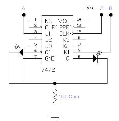
Skema  pengkabelan menggunakan IC 7472

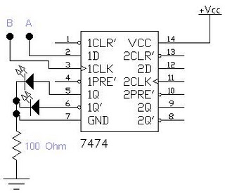
Skema pengkabelan menggunakan IC 7474

IC yang digunakan yaitu IC 7472 dan IC 7474


D FLIP-FLOP (Delay Flip-Flo)
D Flip-Flop memiliki 1 input yang disebut D (Data) serta 2 output yang disebut Q dan Q. Pada dasarnya D lip-flop diperoleh dari SR flip-flop yang salah satu inputnya didapat dengan mengkomplemenkan input yang lain yaitu menambahkan satu gerbang NOT pada masukan.
Prinsip kerja dari D Flip-flop adalah berapapun nilai yang diberikan pada input D akan dikeluarkan dengan nilai yang sama pada output Q. D Flip-Flop diaplikasikan pada rangkaian-rangkaian yang memerlukan penyimpanan data sementara sebelum diprosesberikutnya. Salah satu contoh IC D Flip-flop adalah 74LS75, yang mempunya input Asinkron.
Rangkaian D Flip-Flop:

Selain Flip-flop Set –Riset dan flip-flop J-K ada pula Flip-flop D. sesuai dengan namanya, input flip-flop ini adalah D. flip-flop ini dibangun dengan menggunakan flip-flop Set-Riset seperti gambar dibawah ini :

Dengan adanya gerbang NOT yang masuk ke R , maka setiap inputan yang diumpankan ke D akan memberikan keadaan yang berbeda pada inputan S dan R .
rangkaian D flip flop

tabel kebenaran D flip flop

About these ads
.

Suka Memuat...
Read More >>

Read more ...

Diposting oleh Unknown di 15.53 0 komentar

Label: mikrokontroll

Selasa, 05 Maret 2013

Dot Matrix Moving Display

Pemirsa…..Postingan kali ini akan membahas tentang Tulisan Berjalan menggunakan Dot Matrix, atau lebih dikenal dengan dot matrix running text atau led moving sign, itu tuh yang biasa di spbu, di bank, terminal atau tulisan berjalan di papan iklan kalo malam hari biasanya…
Berawal dari iseng belajar Coding dipagi hari sebelum subuh, akhirnya kepikiran untuk membuat source code dot matrix.

Dot Matrix
Meskipun simple, saya harap tulisan ini bisa bermanfaat, khususnya bagi yang bener-bener ingin belajar dot matrix maupun bagi semua para  pengunjung blog disini….

Dot Matrix Running Text
Design Program / Source code dan Design PCB ini sifatnya Gampang-Gampang Susah, saya sendiri tidak bisa mendesign sekali jadi dan harus melewati beberapa experiment/percobaan dan beberapa rintangan, alhamdulillah semua berhasil dilewati…yuk lihat beberapa gambar percobaan yg saya lakukan..
1st trial…menggunakan 2 buah dot matrix 8×8 & minimu system AT89S52

Percobaan Dot matrix pertama kali
Lihat Kabel2nya, semrawut kabeh….tapi tetep Semangat….

ini sifatnya masih Trial…jadi banyak kabel buat jumper
Ini dia rangkaian Minimum system mikrokontroler yang udah jadi :

Minimum system AT89S52
Kalo ini dot matrix 8×8 jumlahnya 5 pcs, sebenarnya bisa di tambah lagi jumlahnya, cukup dengan menamah dotmatrix dan ic shif register-nya

Dot matrix display
Oke..Rasah Kesuen…!!!! Chek This Out…..
Siapkan Dulu Bahan dan Perlengkapannya…..(kayak mo bikin roti aja ya..)
  1. PCB polos + pelarutnya (FeCl)
  2. AT89S51/AT89S52 (yg murah aja) atau sembarang Microcontroller yg kompatible
  3. Dot matrix 8×8 (pagi pemula, saya sarankan pake 8×8 aja)
  4. IC 74LS164 atau 74HC164 ( IC Shif register )
  5. Cristal 12 Mhz,Capasitor 30 pf dan pendukung Minimum system AT89Sxx
  6. IC Regulator 7805
  7. Transistor D31D atau TIP 3055 atau TIP 2955 (pilih salah satua aja)
  8. Source code dot matrix.hex
  9. Power supply atau adaftor
  10. dll
Langkah Kerja :
Recomended : Buat denga 1 buah dot matrix 8×8 dulu ya, kalo udh berhasil muncul karakter, bisa di tambah sesukamu….
  1. Pastikan dulu pin anoda dan cathoda dot matrix, karena beda produk beda konfigurasi pin-nya dan pasti gk dikasih pinoutnya sama yang jual, saya sarankan beli yang sama (biasanya 1 toko) untuk menentukan pin, biasanya harus cek satu persatu. dot matrix 8×8 ada 16 pin yang menentukan kolom 1 sampai kolom ke 8 dan baris 1 sampai baris ke 8.
  2. Gunakan multitester atau kalo gk ada pake batre 1,5-3 volt dan kabel.
  3. Klo udh ketemu,lihat gambar skema dan buat pcbnya. untuk membuat pcb dot matrix ini tidak semudah kita menggambar skemanya, hal ini dikarenakan jumlah pin pada dot matrix dan terhubung dengan jumlah pin yg terdapat pada IC mikrokontroler dan shif register.
PCB-PCB nya :

PCB dot matrix display

PCB Minimum system
Read More >>

Read more ...

Diposting oleh Unknown di 15.49 0 komentar

Label: mikrokontroll

Senin, 18 Februari 2013

Accessing PC Parallel Port (LPT Port) With Borland Delphi 7.0 Using Small Port Component


Posted by To Share Wednesday, 24 August 2011 0 comments
Adsense Content. recommended 336 X 300
This article will lead you how to make a program to access input output data in parallel port, simple example, this program is used to turn on and turn of LED which is set in Parallel Port, Data Register in computer (Pin D2 until pin D9) in Parallel Port/ LPT.
The steps are as follows:
Enter the following component in Form 1:

No Component Property Value
1 Shape1 Name ShpLED1
Shape stCircle
Height 41
Width 41
Brush Color clWhite
Brush Style bsSolid
2 Shape2 Name ShpLED2
Shape stCircle
Height 41
Width 41
Brush Color clWhite
Brush Style bsSolid
3 Shape3 Name ShpLED3
Shape stCircle
Height 41
Width 41
Brush Color clWhite
Brush Style bsSolid
4 Shape4 Name ShpLED4
Shape stCircle
Height 41
Width 41
Brush Color clWhite
Brush Style bsSolid
5 Shape5 Name ShpLED5
Shape stCircle
Height 41
Width 41
Brush Color clWhite
Brush Style bsSolid
6 Shape6 Name ShpLED6
Shape stCircle
Height 41
Width 41
Brush Color clWhite
Brush Style bsSolid
7 Shape7 Name ShpLED7
Shape stCircle
Height 41
Width 41
Brush Color clWhite
Brush Style bsSolid
8 Shape8 Name ShpLED8
Shape stCircle
Height 41
Width 41
Brush Color clWhite
Brush Style bsSolid
9 EditText1 Name EdLED1
Text -
10 EditText2 Name EdLED2
Text -
11 EditText3 Name EdLED3
Text -
12 EditText4 Name EdLED4
Text -
13 EditText5 Name EdLED5
Text -
14 EditText6 Name EdLED6
Text -
15 EditText7 Name EdLED7
Text -
16 EditText8 Name EdLED8
Text -
17 Button1 Name BtnNyalaLED1
Caption NyalakanLED1
18 Button2 Name BtnNyalaLED2
Caption NyalakanLED2
19 Button3 Name BtnNyalaLED3
Caption NyalakanLED3
20 Button4 Name BtnNyalaLED4
Caption NyalakanLED4
21 Button5 Name BtnNyalaLED5
Caption NyalakanLED5
22 Button6 Name BtnNyalaLED6
Caption NyalakanLED6
23 Button7 Name BtnNyalaLED7
Caption NyalakanLED7
24 Button8 Name BtnNyalaLED8
Caption NyalakanLED8
25 Button9 Name BtnMatiLED1
Caption MatikanLED1
26 Button10 Name BtnMatiLED2
Caption MatikanLED2
27 Button11 Name BtnMatiLED3
Caption MatikanLED3
28 Button12 Name BtnMatiLED4
Caption MatikanLED4
29 Button13 Name BtnMatiLED5
Caption MatikanLED5
30 Button14 Name BtnMatiLED6
Caption MatikanLED6
31 Button15 Name BtnMatiLED7
Caption MatikanLED7
32 Button16 Name BtnMatiLED8
Caption MatikanLED8
33 Button17 Name BtnOpenPort
Caption Open Port
34 Button18 Name BtnClosePort
Caption CloseProgram
35 SmallPort1 Name SmPort1


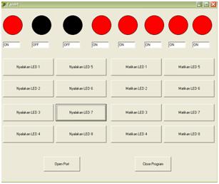
In the monitor will appear image like the following;  
 
Picture1. Accessing PC Parallel Port (LPT Port) With Borland Delphi 7.0 Using Small Port Component : Visualization of the Program which will be made.
Before making listing program (source code) first we decide 2 variables which will be used; those are “data” and “NewData” which mean:
NO. NAMA KOMPONEN SOURCE CODE
1 BtnMatiLED1 data := SmPort1.ReadByte($378);
baru := data AND 254;
SmPort1.WriteByte($378,baru);
ShpLED1.Brush.Color := clBlack;
EdLED1.Text:='OFF';
2 BtnMatiLED2 data := SmPort1.ReadByte($378);
baru := data AND 253;
SmPort1.WriteByte($378,baru);
ShpLED2.Brush.Color := clBlack;
EdLED2.Text:='OFF';
3 BtnMatiLED3 data := SmPort1.ReadByte($378);
baru := data AND 251;
smport1.WriteByte($378,baru);
ShpLED3.Brush.Color := clBlack;
EdLED3.Text:='OFF';
4 BtnMatiLED4 data := SmPort1.ReadByte($378);
baru := data AND 247 ;
SmPort1.WriteByte($378,baru);
ShpLED4.Brush.Color := clBlack;
EdLED4.Text:='OFF';
5 BtnMatiLED5 data := SmPort1.ReadByte($378);
baru := data AND 239;
SmPort1.WriteByte($378,baru);
ShpLED5.Brush.Color := clBlack;
EdLED5.Text:='OFF';
6 BtnMatiLED6 data := SmPort1.ReadByte($378);
baru := data AND 223 ;
SmPort1.WriteByte($378,baru);
ShpLED6.Brush.Color := clBlack;
EdLED6.Text:='OFF';
7 BtnMatiLED7 data := SmPort1.ReadByte($378);
baru := data AND 191;
SmPort1.WriteByte($378,baru);
ShpLED7.Brush.Color := clBlack;
EdLED7.Text:='OFF';
8 BtnMatiLED8 data :=SmPort1.ReadByte($378);
baru := data AND 127;
SmPort1.WriteByte($378,baru);
ShpLED8.Brush.Color := clBlack;
EdLED8.Text:='OFF';
9 BtnNyalaLED1 data := SmPort1.ReadByte($378);
baru := data or 1;
SmPort1.WriteByte($378,baru);
ShpLED1.Brush.Color := clRED;
edLED1.Text:='ON';
10 BtnNyalaLED2 data := SmPort1.ReadByte($378);
baru := data or 2;
SmPort1.WriteByte($378,baru);
ShpLED2.Brush.Color := clRED;
edLED2.Text:='ON';
11 BtnNyalaLED3 data := SmPort1.ReadByte($378);
baru := data or 4;
SmPort1.WriteByte($378,baru);
ShpLED3.Brush.Color := clRED;
edLED3.Text:='ON';
12 BtnNyalaLED4 data := SmPort1.ReadByte($378);
baru := data or 8;
SmPort1.WriteByte($378,baru);
ShpLED4.Brush.Color := clRED;
edLED4.Text:='ON';
13 BtnNyalaLED5 data := SmPort1.ReadByte($378);
baru := data or 16;
SmPort1.WriteByte($378,baru);
ShpLED5.Brush.Color := clRED;
edLED5.Text:='ON'
14 BtnNyalaLED6 data := SmPort1.ReadByte($378);
baru := data or 32;
SmPort1.WriteByte($378,baru);
ShpLED6.Brush.Color := clRED;
edLED6.Text:='ON';
15 BtnNyalaLED7 data := SmPort1.ReadByte($378);
baru := data or 64;
SmPort1.WriteByte($378,baru);
ShpLED7.Brush.Color := clRED;
edLED7.Text:='ON';
16 BtnNyalaLED8 data := SmPort1.ReadByte($378);
baru := data or 128;
SmPort1.WriteByte($378,baru);
ShpLED8.Brush.Color := clRED;
edLED8.Text:='ON';
17 BtnOpenPort SmPort1.Opened:=true;
18 BtnCloseProgram Close;
            “Data” is value that will be read from parallel port in the form of 8 bit data (1 byte)
“New data” is value that will be written to the parallel port after conducted
“Modification” with logical “and” or “or” to conduct bit setting or bit clearing data which is written in the form of 8 bit data (1 byte)
Variable writing decision is conducted under the writing:
var
Form 1:Tform1;
The result is as follows: 
Picture 2. Accessing PC Parallel Port (LPT Port) With Borland Delphi 7.0 Using Small Port Component : variable declaration
The next step is how to make source code program comprehensively so that the program can be used:
Type source code below, appropriate with each component which mean:


result of program execution is like this:  


Picture 3. Accessing PC Parallel Port (LPT Port) With Borland Delphi 7.0 Using Small Port Component : The Result of Program Execution.

 I hope this writing can give benefit to the visitors, readers, developer and me. Thanks for visiting and availability for sharing this article by pressing Share To Facebook, Twitter button or just press like button.
Read More >>

Read more ...

Diposting oleh Unknown di 08.37 0 komentar

Label: delphi, LPT

Senin, 11 Februari 2013

Delphi dan Sistem Embedding – Port Serial RS-232


OK sekarang kita akan membuat contoh sederhana interfacing PC dengan mikrokontroler lewat port serial.
Di contoh ini, mikrokontroler digunakan untuk mengendalikan 4 LED dan membaca 4 saklar. Tugas komputer adalah mengendalikan ke-8 LED tersebut dan membaca posisi saklar.
Program Mikrokontroler
Mikrokontroler menggunakan sebuah AT89S52 dan menggunakan bahasa assembler. Berikut skematiknya.
Skematik ini tidak menampilkan rangkaian RS-232, hanya langsung menggunakan symbol COMPIM. Untuk rangkaian RS-232 converter bisa diliat di sini.
AT89S52 bekerja pada frekuensi 11.0592 MHz dan baud rate pada 9600 bps. Tugas utama mikro adalah selalu mengecek data dari port serial, sub-rutinCommand_Receive dan memproses perintah yang diterima, sub-rutinCommand_Process. Perintah menggunakan 1 karakter ASCII, ‘A’ – ‘G’.
Berikut adalah daftar perintah dari PC:
  • ‘A’: toggle LED yang terhubung ke P2.0
  • ‘B’: toggle LED yang terhubung ke P2.1
  • ‘C’: toggle LED yang terhubung ke P2.2
  • ‘D’: toggle LED yang terhubung ke P2.3
  • ‘E’: semua LED ON
  • ‘F’: semua LED OFF
  • ‘G’: membaca posisi saklar, jika saklar ON semua mikro akan mengirim ’00′ dan jika OFF semua mikro akan mengirim ’0F’.
Program mikro bisa di download di sini.
Pada dasarnya, mikro memfungsikan port serial pada mode 1 dengan baud rate 9600 bps. Pada saat dimulai program langsung menyalakan semua LED. Dan mikrokontroler sebagian besar menghabiskan waktunya untuk membaca command dari port serial.
Program Komputer
Tampilan program komputer bisa dilihat di bawah ini dan source codenya bisa di download di sini.
Bagian utama dari program Delphi adalah:
Prosedure EnumComport
Prosedure ini adalah prosedure untuk membaca registry untuk mengetahui COM apa saja yang terinstal di komputer. Berikut cuplikan kodenya:
procedure TForm5.EnumComPorts(Ports: TStrings);
var
KeyHandle: HKEY;
ErrCode, Index: Integer;
ValueName, Data: string;
ValueLen, DataLen, ValueType: DWORD;
TmpPorts: TStringList;
begin
ErrCode := RegOpenKeyEx(
HKEY_LOCAL_MACHINE,
‘HARDWARE\DEVICEMAP\SERIALCOMM’,
0,
KEY_READ,
KeyHandle);
if ErrCode <> ERROR_SUCCESS then
begin
//raise EComPortExt.Create(‘EnumComPorts’,CError_RegError, ErrCode);
MessageBox(Handle,’Registry Error’,pchar(Application.Title),MB_OK or MB_ICONERROR);
exit;
end;
TmpPorts := TStringList.Create;
try
Index := 0;
repeat
ValueLen := 256;
DataLen := 256;
SetLength(ValueName, ValueLen);
SetLength(Data, DataLen);
ErrCode := RegEnumValue(
KeyHandle,
Index,
PChar(ValueName),
{$IFDEF DELPHI_4_OR_HIGHER}
Cardinal(ValueLen),
{$ELSE}
ValueLen,
{$ENDIF}
nil,
@ValueType,
PByte(PChar(Data)),
@DataLen);
if ErrCode = ERROR_SUCCESS then
begin
SetLength(Data, DataLen);
TmpPorts.Add(Data);
Inc(Index);
end
else
if ErrCode <> ERROR_NO_MORE_ITEMS then
MessageBox(Handle,’Registry error’,pchar(Application.Title),MB_OK or MB_ICONERROR);
until (ErrCode <> ERROR_SUCCESS) ;
TmpPorts.Sort;
Ports.Assign(TmpPorts);
finally
RegCloseKey(KeyHandle);
TmpPorts.Free;
end;
end;
prosedur ini digunakan di event Combobox1 onDropdown:
procedure TForm5.ComboBox1DropDown(Sender: TObject);
begin
EnumComPorts(ComboBox1.Items);
end;
Pada saat ComboBox1 mengalami even Ondropdown, maka akan ditambahkan item2 baru berupa nama com yang terinstal di PC.
Prosedur Buka COM
ApdComport dibuka oleh button1, button dengan caption “Open”. Berikut cuplikan programnya:
procedure TForm5.Button1Click(Sender: TObject);
var
ComNo:integer;
S:string;
begin
if ComboBox1.ItemIndex=-1  then
begin
MessageBox(Handle,’Please select a COM’,pchar(Application.Title),
MB_OK or MB_ICONERROR);
ComboBox1.SetFocus;
exit;
end;
S:=Copy(ComboBox1.Text,4,Length(ComboBox1.Text)-3);
ComNo:=StrToInt(s);
try
ApdComPort1.ComNumber:=ComNo;
ApdComPort1.Open:=true;
Except
Port_State:=false;
end;
end;
Pertama program mengecek apakah COM sudah dipilih dengan membaca ComboBox1.Itemindex, jika bernilai -1, berarti belum ada com yang dipilih. Program akan menampilkan pesan error. Jika sudah ada com yang terpilih, program akan mengambil nomor comnya, dengan membuang string “COM”.
Lalu apdComport coba dibuka dengan membuat property open menjadi true. Jika gagal, misal karena com yang bersangkutan telah dipakai oleh aplikasi lain, maka sebuah variabel Port_State akan bernilai false. Variable ini digunakan untuk mengecek apakah com telah sukses dibuka atau tidak. Setiap pengiriman atau penerimaan data akan selalu mengecek variable ini. Pengiriman baru bisa dilakukan apabila com telah sukse dibuka, jika tidak akan error.
Menyalakan atau Mematikan LED
Menyalakan atau mematikan LED dilakukan dengan mengirim perintah yang telah ditentukan di atas. LED bisa diatur secara individu atau secara bersamaan. Misal untuk untuk mengatur LED yang terhubung ke P2.0 dilakukan dengan mengirim karakter “A”:
procedure TForm5.CheckBox1Click(Sender: TObject);
begin
if not Port_State then exit;
ApdComPort1.Output:=’A';
end;
Sedangkan program untuk menyalaka semua LED:
procedure TForm5.Button3Click(Sender: TObject);
begin
if not Port_State then exit;
ApdComPort1.Output:=’E';
end;
Prosedur Membaca Saklar
Untuk membaca saklar, pertama program akan mengirim perintah membaca saklar, kemudian membaca data yang dikirim oleh mikro.
procedure TForm5.Button5Click(Sender: TObject);
var
S:string;
TheData,code: integer;
begin
if not Port_State then exit;
ApdComPort1.Output:=’G';
S:= ReadSerialData(100);
val(‘$’+S,TheData,code);
Label2.Caption:=’SW1 OFF’;
Label3.Caption:=’SW2 OFF’;
Label4.Caption:=’SW3 OFF’;
Label5.Caption:=’SW4 OFF’;
TheData:= not TheData;
if (TheData and 1 = 1)  then
Label2.Caption:=’SW1 ON’;
if (TheData and 2 = 2)  then
Label3.Caption:=’SW2 ON’;
if (TheData and 4 = 4)  then
Label4.Caption:=’SW3 ON’;
if (TheData and 8 = 8)  then
Label5.Caption:=’SW4 ON’;
end;
Program pembacaan data dilakukan di fungsi ReadSerialData:
function TForm5.ReadSerialData(TimeOut: integer): string;
var
i: integer;
begin
Result:=”;
while ApdComPort1.InBuffUsed=0  do
begin
Dec(TimeOut);
Sleep(1);
Application.ProcessMessages;
if TimeOut=0  then exit;
end;
Sleep(10);
for I := ApdComPort1.InBuffUsed downto 1 do
Result:=Result+ApdComPort1.GetChar;
end;
Fungsi ini akan membaca data yang diterima oleh port serial selama waktu tertentu,TimeOut. Buffer input port serial dibaca dulu (InBuffUsed), apabila selalu 0 dalam waktu TimeOut, berarti tidak ada data. Jika ada maka data dibaca per karakter (byte) melalui perintah ApdComport.GetChar. Data yang diterima akan selalu ASCII. Misal jika semua saklar pada posisi ON maka data yang diterima adalah “0F”. Program harus mengecek data yang diterima tersebut untuk menentukan semua posisi saklar.
Read More >>

Read more ...

Diposting oleh Unknown di 08.31 0 komentar

Label: LPT

Minggu, 10 Februari 2013

Program Parallel Port In Visual Basic

If you have built any of the interfaces on my circuits page and now want to know how to actually make use of them, this page is for you. This is a simple introduction to programming the parallel port in Visual Basic. Note that most of the concepts in this page apply to both 16 bit and 32 bit versions of VB. If you are interested in using QBasic to control the port, see Programming The Parallel Port In QBasic. What this document will not do is give you lots of details on using bi-directional ports, DMA and other advanced topics. This document assumes that you are familiar with the basic functions of Visual Basic itself.
Now before we go any further, we must figure out a way around some limitations built into Visual Basic. VB cannot directly access the hardware on a system. All hardware requests must go through Windows. Because of this, the closest we can get to manipulating the parallel port is with the Printer object. While this is all fine and good when you want to actually print something, it is useless when we want direct hardware control. There may be API calls to get round this, but as of yet I have been unable to find any. In order to control the port directly, we must use something external to our program. It just so happens that there is a great, free product that does exactly what we want. It is a DLL from a company called SoftCircuits. You can download this DLL from theirProgramming Tools and Libraries page. Use VBASM.DLL (in the VBASM.ZIP package) for VB1, VB2, VB3 or VB4 16Bit. Use WIN95IO.DLL (in the WIN95IO.ZIP package) for VB4 32bit, VB5 or VB6. No matter which one you choose, the DLL file itself must be in the windows\system directory in any machine the interface control software is to be used or developed on. Please note that no matter which DLL you use, this won't work under any Windows NT based system, including WinNT, Win2K, XP, Vista, Win7 or Windows Server. NT based systems do not allow direct hardware access to non-drivers.
Now that we have that finished with, let's get to the port. The parallel port is made up of three different sections. These are the data lines, control lines and status lines. There are 8 data lines, and they are the primary means of getting information out of the port. In simple projects, you will be concentrating mostly on the data lines. The control lines are another 4 outputs. They are meant to provide control signals to the printer (such as form feed or initialize). The status lines are a standard parallel port's only inputs. There are 5 of them. They were meant to allow the printer to communicate things such as error, paper out and busy to the PC.
Each section is accessed by it's own address and will act independently from the rest. This is almost as if they were different ports. The addresses are as follows:
Port
Address (Decimal)
Address (Hex)
Data Lines
888
378h
Control Lines
890
37Ah
Status Lines
889
379h

You need to know the address of the port you want to use. You will also need two other things; the command to access the port and the number you want to set it to. The command will be explained in a little while. The ports work with numbers. These can be expressed in hex, binary or decimal, but for this document all values will be expressed in decimal. It's just easier that way. Anyway, you operate the port by sending it a number that represents the binary pattern of the physical outputs on the port. For example, to set the 8 data lines to 11111111, you would send 255. To set them to 00000000 you would send 0. Note that these are all 8 bit binary numbers, and the port is also 8 outputs. Coincidence? I think not.
Before we can use any of the functions contained within either DLL, we must declare them. These declarations are to be placed in any module in your program in the General_Declarations section.
For 16bit VB (VBASM.DLL), use:
Declare Function vbInp Lib "VBASM.DLL" (ByVal nPort As Integer) As Integer
Declare Sub vbOut Lib "VBASM.DLL" (ByVal nPort As Integer, ByVal nData As Integer)
For 32bit VB (WIN95IO.DLL), use:
Declare Sub vbOut Lib "WIN95IO.DLL" (ByVal nPort As Integer, ByVal nData As Integer)
Declare Sub vbOutw Lib "WIN95IO.DLL" (ByVal nPort As Integer, ByVal nData As Integer)
Declare Function vbInp Lib "WIN95IO.DLL" (ByVal nPort As Integer) As Integer
Declare Function vbInpw Lib "WIN95IO.DLL" (ByVal nPort As Integer) As Integer
Once you declare the functions, you will have two new commands available. These are vbInp and vbOut. vbOut is a statement and is used to send a bit to a port, like the following:

vbOut [port],[number]
We will get to vbInp later. As you can see, the two parameters required are the port address and the value we want to set it to. The address can be decimal or hex, as can the value. Because there are only 8 data lines, we can only send a maximum of 255 to the port (255 is decimal for binary 11111111). The examples below illustrate sending a few different bit patterns to the data lines.

'set port to 00000000
vbOut 888, 0
'set port to 10000000
vbOut 888, 1
'set port to 01000000
vbOut 888, 2
'set port to 00100000
vbOut 888, 4
'set port to 00010000
vbOut 888, 8
Of course, you can also turn on more than one bit:

'set port to 10110000
vbOut 888, 11
Note that when you send a bit pattern to the port everything that was there previously is cleared. This is a convenience and also a annoyance. For example, what if we want bit 2 to always stay at 1, but want to turn bit 5 on and off in sequence? Every time we set bit 5, bit 2 is turned off, and vice versa. We will discuss how to get around this when we get to the vbInp function.
The control lines are just as easy to control, but there are a few differences. First, the address of the port is 890. Second is that there are only 4 outputs, so the highest decimal representation of the binary bit pattern you will be using is 15 (binary 1111).
Outputting information is easy, and inputting is just as easy. If you actually want to get information into the computer, you will be using the 5 status lines. Reading the bit pattern of a port is done using the vbInp function. This function is used in the following way:

[variable]=vbInp([port])
So if we wanted to get the current status of the status lines (port 889) we would use:

PortNum%=vbInp(889)
PortNum% would then contain the decimal representation of the binary bit pattern present at the 5 status lines. If you try this and get 31 (11111) with nothing connected to the port don't be surprised. When there is nothing connected to the input of a TTL logic chip, a high input is usually assumed.
Not only can you perform inputs on ports actually designed for inputting, but you can also use vbInp to read the status of an output port. For example:

PortNum%=vbInp(888)
The above would set PortNum% to the current value of the data lines (port 888). We can prove this by doing the following:

vbOut 888, 56
PortNum%=vbInp(888)
MsgBox PortNum%
If all is well, the number 56 will appear in a message box on the screen.
Now that we know the vbInp function we can use it to solve the problem of keeping the state of one bit while changing the state of another. For that we will define a subroutine that uses both functions:

SUB OutPort(PortAddress%, OutNum%)

PortState% = vbInp(PortAddress%)
PortNum% = PortState% + OutNum%
vbOut PortAddress%, PortNum%

END SUB
Note how the sub adds the current port state to the number we send it. This has the effect of keeping all previous bits at the same state they were in, but either turning on or off the bit or bits represented by the number we pass to the sub. This also requires a change in the way the function is used. To turn on bit 1, we would:

OutPort 888, 1
This example assumes a current port status of 0 (00000000). If bit 1 is already high, you will get unexpected results, so keeping track of the port is important. To turn bit 1 back off, we would:

OutPort 888, -1
Now this sub introduces a problem. How do we clear everything on the port as if we were doing vbOut 888, 0? Sending 0 to the sub has no effect (adding or subtracting 0 will always give you the original number), so we will need to add a statement to specifically react to a 0. This done by a simple IF...THEN decision:

SUB OutPort(PortAddress%, OutNum%)

PortState% = vbInp(PortAddress%)
PortNum% = PortState% + OutNum%
vbOut PortAddress%, PortNum%
IF OutNum% = 0 THEN vbOut PortAddress%, 0

END SUB
The sub does all it's normal stuff, but also sets the port to 0 if a 0 was passed to it. This is a very easy to clear up a port if you create strange bit patterns by trying to turn a bit on twice. You may want to keep track of the state you expect the port to be and compare it to the actual state by using the vbInp function. If the two do not match, clear the port and reset all the the bits using your other variable.
Now that we know a few useful functions with respect to output, we should look at a very useful input function. When using the port in software, you will very likely need to know the status of a single bit at one time or another. There are various ways of doing this, but I find the function below to be the most useful:

FUNCTION BitStatus(PortAddress%, BitYouWant%) AS INTEGER

IF PortAddress% = 888 THEN

NumOfBits% = 8

ELSE IF PortAddress% = 889 THEN

NumOfBits% = 5

ELSE

NumOfBits% = 4

REDIM PortBits(NumOfBits%) AS INTEGER
PortNum% = vbInp(PortAddress%)
FOR i = 1 To NumOfBits%

PortBits%(i) = PortNum% MOD 2
PortNum% = FIX(PortNum% / 2)

NEXT I
BitStatus% = PortBits%(BitYouWant%)

END FUNCTION
The function first decides how many bits it has to work with by looking at the address of the port. Note that in all other examples it was really irrelevant if you used decimal or HEX addresses. In this function you will need to change the numbers if you work in HEX. Now, back to how the function functions (he he he). After deciding how many bits there are in the port, it makes an array of the same number of elements. It then goes through a loop, performing integer division on the number returned from the port. It performs one division for each bit in the port. This is probably the easiest way to convert to binary, as VB has no built in decimal to binary function. Again, if you work in HEX you will have to adjust the function here. The function then assigns itself the value of the array element you specify with the BitYouWant% variable.
Well, that's it. The above is not limited to the parallel port. You can use it with any sort of interface that uses a standard I/O port. Of course, this code would not be ideal in controlling the serial port, as a lot of low level coding would be necessary.
For example, to read bit 5 of port 888, you would use:

Bit5Variable% = BitStatus%(888, 5)
Read More >>

Read more ...

Diposting oleh Unknown di 07.42 0 komentar

Label: LPT

Langganan: Postingan (Atom)

Postingan Populer

  • KUMPULAN PERSAMAAN IC
    KUMPULAN PERSAMAAN IC DENGAN CODE TERTENTU by:Asiatronik TOSHIBA=TAxxxx/dll PANASONIC=ANxxxx/dll SHARP=IXxxxx ECG=xxxx NTE=xxxx SANYO=LAx...
  • Segala tetek bengek skutik
    Pembuktian CDI Yamaha Fino Thailand, Ampuh Buat Balap? Gbr 1 OTOMOTIFNET  -  Santernya kabar CDI Yamaha Fino Thailand yang sanggup mengha...
  • Modifikasi PC power supply 12V menjadi 13.8V
    Pilihan modifikasi power supply (ps) switching PC diambil dengan pertimbangan sbb: mudah diperoleh dan berharga relatif murah effisiensi sw...
  • Inverter Switching
    Yang ingingin membuat inverter dengan menggunakan trafo jenis switching dapat di coba sekema brikut ini,, skema ini menggunakan beberapa ...
  • Tone Control TL072
    Tone controle ini menggunakan jangtung rangkaian IC Op-Amp TL072, rangkaian nya cukup sederhana namum kemampuannya boleh diandalkan, coba ...
  • Delphi dan Sistem Embedding – Port Serial RS-232
    OK sekarang kita akan membuat contoh sederhana interfacing PC dengan mikrokontroler lewat port serial. Di contoh ini, mi...
  • MODIFIKASI POWER SUPPLY KOMPUTER
    Pengalaman membuat rangkaian power supply dengan kapasitas arus besar membutuhkan trafo adaptor berukuran besar dan berat, elco yang juga ...
  • Ganti kabel flexibel Camcorder JVC GZ-MS120
    Bismillah, Dapat pasien Camcorder yang nyala normal,tapi lcd gelap.kebanyakan kelemahan dari Camcorder dengan flip lcd adalah rusak kabel ...
  • Amplifier Mini
    Amplifier ini banyak digunakan pada Radio-radio transistor, tape dan walkman. Prinsip kerja Amplifier ini jika ada sinyal masuk ke input ...
  • Pewaktu yang dapat diprogram
    Sekarang waktunya kita membuat aplikasi IC 4017 yang lebih kompleks, yaitu pewaktu/timer. Cukup menggunakan beberapa...

MEMBERS

Recomendeed Download

PENTING!!!!

Ads

CATEGORY

- - -
  • SOFTWARES
    • AntiVirus
    • Audio/video
    • Converter
    • Design/Image Editor
    • Desktop Custom
    • Free Games
    • Internet Tools
    • Security
    • Software By Request
    • System Tools
    • Utility
  • TIPS N TRIK
    • Blogger
    • Facebook
    • Hacking
    • Komputer
© 2011 copyright www.belajarber-sama.blogspot.com Themes By Gresik edited by belajarber-sama.blogspot
Free Download Software Full Crack Keygen Patch Serial